Machine Vision Optics Guide

What Is F-Number in Machine Vision? Aperture, Depth of Field, and Diffraction Explained

The aperture parameter that sets light throughput, depth of field, and diffraction, plus working f-number, numerical aperture, the entrance pupil, and low-light lens selection in one guide.

By Commonlands engineering team · Updated July 2026 · 21 min read

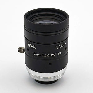
A C-mount lens down its optical axis, iris open to the circular f-number aperture

F-number (written f/# or N) is the ratio of a lens's focal length to the diameter of its entrance pupil. A 25mm lens with a 12.5mm entrance pupil is an F/2 lens; stopped down to a 3.1mm pupil, the same lens becomes F/8. In machine vision, f-number is the control knob for the core imaging tradeoff: light throughput versus depth of field versus diffraction-limited sharpness.

F-number is not focal length, and it is not effective focal length (EFL). Two lenses with the same EFL can have very different aperture ranges, and two lenses at the same f-number can frame completely different scenes. This guide covers the definition and its consequences, then the three concepts engineers reach for next: working f-number at finite magnification, numerical aperture, and the entrance pupil that defines f/# in the first place.

What is the f-number of a lens?

F-number (f/#) is the ratio of a lens's focal length to its entrance pupil diameter. It is dimensionless, it appears on virtually every machine vision lens datasheet, and it determines how much light the lens delivers to the sensor per unit time. A lower f-number means a larger aperture and more light; a higher f-number means a smaller aperture, less light, and more depth of field.

f/# = f / D_EP f = effective focal length; D_EP = entrance pupil diameter. A 25mm lens with a 12.5mm entrance pupil is F/2. The same lens stopped down to a 3.1mm pupil is F/8.

Because f-number is a ratio, the same value corresponds to different physical apertures at different focal lengths. A 12mm lens at F/1.4 has an entrance pupil of about 8.6mm; a 35mm lens at F/1.4 has an entrance pupil of about 25mm. Both deliver the same image-plane irradiance at infinity focus, which is exactly why the ratio is the useful quantity.

The standard stop sequence (F/1.4, F/2, F/2.8, F/4, F/5.6, F/8, F/11, F/16) advances by factors of √2 in pupil diameter. Each step halves the light reaching the sensor. Stopping a lens down from F/2.8 to F/5.6 costs two stops, a factor of 4 in light. The sequence is inherited from photography but applies directly to machine vision optics.

Notation varies across datasheets: the same aperture appears as F/2.8, f/2.8, or "F# 2.8" in specification tables. The slash form is standard in optics literature. C-mount iris rings usually carry full-stop or half-stop markings; M12 lens listings typically state a single fixed value because most M12 designs do not provide an adjustable iris.

In machine vision, f-number is not a brightness dial. It shifts four system properties at once: sensor irradiance, depth of field, residual aberration levels, and the diffraction-limited spot size. No single setting maximizes all four, which is why aperture selection is a system-level decision.

F-number range Light throughput Depth of field Aberration behavior Diffraction penalty
F/1.4–F/2.8 高い Shallow Often highest: spherical aberration, coma, and astigmatism tend to be largest wide open Negligible
F/4–F/8 中程度 Medium to deep Usually reduced: many lenses reach near-peak resolution here Minor to moderate, depending on pixel size
F/11–F/16+ Deep Low: small ray cones suppress residual aberrations geometrically Significant: the Airy disk often exceeds the sensor pixel pitch

The table reflects a tendency, not a law. The f-number where aberrations are adequately controlled and diffraction has not yet taken over depends on the specific lens design and the sensor pixel size. Many lenses reach their flattest, most uniform performance one to two stops down from wide open. The only reliable confirmation is MTF data measured at the working aperture, across the field, not just on axis.

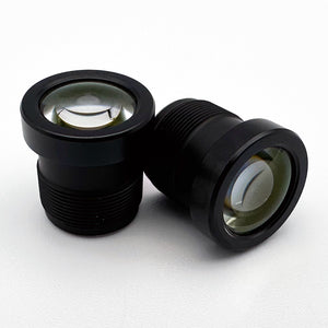
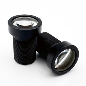
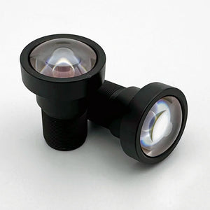
Four identical M12 board lenses shipped as separate fixed-aperture variants on a gray surface
Board lenses fix the F/# at manufacture rather than using an iris ring.

How does f-number affect depth of field?

Depth of field increases approximately linearly with f-number. Doubling the f-number roughly doubles the range of object distances that stay acceptably sharp, at the same focal length, working distance, and circle of confusion. Stopping down is the first tool to try when parts show height variation, before changing the optical or mechanical setup.

DOF ≈ 2 × c × f/# × WD² / f² c = acceptable circle of confusion (typically 1–2 pixels in machine vision); WD = working distance; f = focal length. An approximation valid away from the macro regime.

Three practical scaling rules follow from the formula. Depth of field grows linearly with f-number. It grows with the square of working distance, so moving the camera back is a powerful lever when the field of view budget allows it. It shrinks with the square of focal length, so longer lenses are meaningfully less forgiving at the same distance and aperture.

For inspection of parts with height variation (PCBs with tall components, castings, flexible packaging), a 35mm C-mount lens that holds roughly 2mm of depth at F/2 can hold 8–10mm at F/8. That difference often decides whether an application needs mechanical fixturing or simply a smaller aperture. The full derivation, including hyperfocal focus and circle-of-confusion selection, is in the depth of field guide.

Working method

Stop down until the required depth of field is met, confirm that f-number sits below the diffraction limit for your pixel size, and stop there. Run the depth of field calculator with your focal length, f-number, working distance, and pixel pitch before committing to hardware.

How does f-number affect light throughput and exposure time?

Image-plane irradiance scales with 1/(f/#)². Each full stop increase in f-number halves the light reaching the sensor, so going from F/2 to F/4 costs a factor of 4 and going from F/1.4 to F/8 costs a factor of 32. Every stop given up must be recovered with longer exposure, brighter illumination, or higher gain.

Each recovery path has a cost. Longer exposure increases motion blur: at conveyor speeds of 200–500mm/s, an extra 1ms of exposure adds 0.2–0.5mm of smear at the object. More illumination power means more heat and larger drive electronics for strobe or structured-light systems. Higher sensor gain amplifies noise along with signal and reduces usable dynamic range.

Machine vision has one structural advantage over photography here: illumination is usually programmable. LED ring lights, backlights, and strobes can be turned up when the aperture is stopped down, which makes small apertures practical in industrial systems in a way they rarely are under ambient light. The lighting budget still has to be designed, not assumed.

T-stop versus f-number

F-number is a geometric ratio and ignores absorption and reflection losses inside the lens. The T-stop corrects for actual transmission. For machine vision lenses with modern anti-reflection coatings the difference is typically under half a stop, and T-stop rarely appears on datasheets, so f-number remains the working parameter. The gap is worth measuring when exposure margin is tight, when the design has many elements, or when the system operates at NIR wavelengths where coating performance can differ from the visible specification.

When does diffraction limit resolution?

Diffraction limits resolution once the Airy disk, the smallest spot even a perfect lens can form, grows larger than the sensor's pixel pitch. The Airy disk diameter is approximately 2.44 × λ × f/#, so it grows linearly with f-number. Past that point, stopping down further reduces resolution while also reducing light.

Airy disk diameter ≈ 2.44 × λ × f/# λ = wavelength. At 550nm this evaluates to roughly 1.34µm × f/#. Reference: Hecht, Optics, 5th ed.
F-number Airy disk diameter (550nm) Relative to 3.45µm pixel Relative to 5.0µm pixel
F/22.7µm0.8× pixel0.5× pixel
F/45.4µm1.6× pixel1.1× pixel
F/5.67.5µm2.2× pixel1.5× pixel
F/810.7µm3.1× pixel2.1× pixel
F/1114.7µm4.3× pixel2.9× pixel
F/1621.4µm6.2× pixel4.3× pixel

For a sensor with 3.45µm pixels, diffraction becomes the limiting factor somewhere around F/4–F/5.6. For 5.0µm pixels, it arrives later, around F/5.6–F/8. This does not mean those apertures are forbidden. It means stopping down past them buys depth of field at a resolution cost, and that cost should be a deliberate choice. The diffraction limit section of the spatial resolution guide works through the sensor-side math.

NIR systems hit the limit sooner in spatial terms because λ is larger: at 850nm, the Airy disk at F/8 is approximately 16.5µm, roughly 55% larger than at 550nm. An IR-corrected lens handles the focus shift between visible and NIR, but at any given f-number the diffraction limit is set by the wavelength, and no lens design can shrink the NIR Airy disk below it.

Fixed-aperture lens families make the aberration-versus-diffraction tradeoff visible in catalog data. The CIL160 16mm M12 lens is offered in fixed F/1.9, F/2.8, F/4.0, and F/5.6 variants; its published resolution ratings peak at the middle apertures (12MP at F/2.8–F/4.0) and drop to 8MP at F/5.6, consistent with an Airy disk of about 7.5µm beginning to compete with fine pixel pitches at that stop.

CIL160 16mm M12 lens family offered in fixed F/1.9, F/2.8, F/4.0, and F/5.6 aperture variants
The CIL160 16mm M12 lens ships in four fixed-aperture variants. Resolution ratings peak at the mid apertures, not wide open. This is the aberration-diffraction crossover in catalog form.

What is the working f-number of a lens?

Working f-number (also called effective f-number) is the f-number of a lens at a finite object distance, after accounting for the lateral magnification at which the system runs. At infinity focus it equals the catalog value. At any finite magnification it is larger, so the image is dimmer and the diffraction spot bigger than the datasheet number alone predicts.

f/#_working = f/#_nominal × (1 + m) m = image size / object size = sensor coverage / FOV width f/#_nominal = EFL / entrance pupil diameter, defined at infinity focus. m is the lateral magnification at the operating distance.

The physical cause is image formation geometry, not a lens defect. Focusing on a close object pushes the image plane farther from the rear principal plane. The entrance pupil diameter is fixed by the iris setting, but the effective image-distance-to-pupil ratio grows by (1 + m). From the thin lens relation:

d_i = f × d_o / (d_o − f) m = d_i / d_o = f / (d_o − f) f/#_working = f/#_nominal × (d_i / f) d_o = object distance from the front principal plane; d_i = image distance. For a 25mm lens at 300mm, m = 25/275 ≈ 0.09, a 9% aperture penalty. At 150mm, m = 0.2 and exposure needs grow 44%.
Magnification (m) Working f/# multiplier Exposure factor vs catalog f/# Stops slower
0 (infinity)1.00×1.0×0
0.101.10×1.21×0.3
0.201.20×1.44×0.5
0.501.50×2.25×1.2
1.00 (1:1)2.00×4.0×2.0

Diffraction follows the same correction: the Airy disk at the sensor is 2.44 × λ × f/#_working, so at 1:1 magnification a nominal F/4 lens produces the diffraction spot of an F/8 lens. Depth of focus, the axial tolerance on sensor position, also scales with working f-number. A quick estimate of magnification is sensor width divided by field-of-view width: a 1/1.8" sensor about 7.2mm wide imaging a 36mm field runs at m = 0.2.

Illumination sizing

When magnification exceeds about 0.1 (typical whenever the field of view is less than roughly 10× the sensor size), size illumination and exposure from working f-number, not the catalog value. The required light scales as (1 + m)². Below m ≈ 0.05, the penalty is under 10% and the catalog f-number is fine for first-order budgeting.

Setup order matters for lenses with an iris: set focus at the widest aperture, where focus error is easiest to see, then stop down to the operating position before verifying image quality. The how-to-focus guide covers the full procedure.

What is numerical aperture?

Numerical aperture (NA) is the angular measure of the light cone an optical system accepts: NA = n × sin(θ), where n is the refractive index of the medium and θ is the half-angle of the acceptance cone. In air, NA = sin(θ), bounded between 0 and just below 1.0 for camera lenses.

NA = n × sin(θ) NA = 1 / (2 × f/#)    f/# = 1 / (2 × NA)    (in air; exact under the Abbe sine condition) NA = sin( arctan( 1 / (2 × f/#) ) )    (idealized thin lens, in air) For an aberration-corrected lens satisfying the Abbe sine condition, NA = 1/(2 × f/#) is the exact relation (Smith, Modern Optical Engineering). The arctan form is the flat-principal-plane thin-lens construction; it gives 0.336 at F/1.4 versus 0.357 from the sine-condition relation. The Airy disk formula used on this page, 2.44 × λ × f/# ≡ 1.22 × λ / NA, assumes the sine-condition relation.

NA and f-number describe the same acceptance cone from different directions: NA as an angle in the medium, f/# as a ratio of focal geometry. Machine vision datasheets and iris rings use f-number; microscopy, fiber optics, and illumination optics use NA, partly because immersion media with n > 1 push microscope NA above 1.0. Converting at the start of a calculation and staying in one convention avoids errors.

f/# NA (approx.) Common use
F/1.40.36Fast prime; maximum throughput setting
F/1.80.28High-speed imaging
F/2.80.18Balanced throughput and depth of field
F/40.13Common inspection setting
F/80.063Wide depth of field; visible diffraction on small pixels
F/160.031Maximum depth of field; strongly diffraction-limited

NA is the natural variable for diffraction. The Rayleigh criterion puts the smallest resolvable feature at approximately 0.61 × λ / NA: at 550nm, NA 0.36 (F/1.4) resolves about 0.9µm while NA 0.063 (F/8) resolves about 5.3µm. Irradiance at the sensor scales as NA², so doubling NA quadruples photon flux per pixel, provided aberration correction holds up at the wider aperture, which is a lens design question, not a geometry question.

Two cautions apply at finite conjugates and on quality. The iris and focal length fix the entrance pupil diameter rather than the object-side NA: NA_obj ≈ D_EP / (2 × WD), so the object-side cone widens as the object moves closer, while image-side throughput and diffraction at close range are governed by working f-number, covered above. NA is also not an image quality score: it says nothing about MTF, distortion, or relative illumination. The EFL calculator documents the f/# = f/D = 1/(2 × NA) relationship used throughout this page.

What is the entrance pupil of a lens?

The entrance pupil is the image of the aperture stop as seen from the object side of the lens. Elements in front of the stop image it into object space, usually as a virtual, magnified or demagnified image; that image is what incoming ray bundles actually see. It has a diameter and an axial position, and both matter.

Looking into the front of a lens against a bright background, the circular bright opening you see is the entrance pupil. It coincides with the physical stop only when no optics sit in front of the stop. In a multi-element design, a front group with 1.5× pupil magnification turns a 10mm iris opening into a 15mm entrance pupil, which is why published f-numbers are derived from pupil size, not from the physical iris blade opening.

Term What it is Why engineers care
Aperture stop The physical element (usually the iris assembly) that limits ray bundle diameter Its diameter, scaled by front-group magnification, sets entrance pupil size
Entrance pupil Image of the stop seen from object space Defines f/# = f / D_EP and object-space chief-ray geometry
Iris diameter Clear aperture of the physical iris blades at a given setting Generally not the entrance pupil in lenses with a front group; unless the pupil magnification is exactly 1×, plugging it into f/# = f/D gives the wrong answer
Exit pupil Image of the stop seen from the image side Its axial position relative to the sensor sets the chief ray angles (CRA) arriving at the image plane, the quantity behind sensor CRA compatibility

To recover the pupil diameter from datasheet values, invert the definition: D_EP = f / f/#. The CIL522 12mm C-mount lens has a pupil of about 8.6mm at F/1.4; the CIL544 25mm lens at F/1.8 has a pupil of about 13.9mm. Each iris position is, literally, a different entrance pupil diameter.

Pupil position drives pupil matching. In object space, the chief ray from each off-axis point is defined as the ray through the center of the entrance pupil, so entrance pupil location sets object-side chief-ray geometry. The chief ray angle (CRA) arriving at the sensor, however, is determined entirely by the image-side geometry: CRA ≈ arctan(image height / exit pupil distance), so the exit pupil position relative to the image plane, summarized in the lens's published CRA curve, is what must match the sensor. Sensor microlenses are progressively shifted center-to-corner to match a specific CRA profile; a lens whose exit pupil sits at the wrong axial position produces corner shading and color error on a sensor it otherwise covers. Lenses that publish pupil geometry give you inputs for the analysis in the chief ray angle guide.

An entrance pupil at optical infinity is the defining property of an object-space telecentric lens, achieved by placing the stop at the rear focal plane of the front group. All object-space chief rays then travel parallel to the axis, so magnification does not change with small axial shifts of the part, which is why telecentric optics are used for precision dimensional measurement. The telecentric lens guide covers the concept in depth.

Pupil rules of thumb

Use D_EP = f / f/# for aperture calculations, never the iris blade diameter. When a sensor has published CRA limits, check the lens's CRA curve, which is set by exit pupil position, not by entrance pupil diameter. If no CRA curve or pupil position is listed, request it from the manufacturer or verify CRA behavior empirically during integration.

How do you choose a lens for low-light machine vision?

A low-light machine vision lens is one that collects enough photons per frame for an acceptable signal-to-noise ratio without an exposure time that causes motion blur. The lens contributes through aperture, transmission, and stray-light suppression, but low-light performance is a system outcome that also depends on pixel size, target velocity, and illumination strategy.

Aperture is the primary optical lever. Throughput scales with (1/f/#)², so moving from F/2.8 to F/1.4 quadruples the photons collected per unit time, which can cut exposure to a quarter at the same signal level. SNR in a shot-noise-limited CMOS sensor improves with the square root of photon count, so that same change roughly doubles SNR at a fixed exposure. Transmission matters too: anti-reflection coating quality and the number of air-glass surfaces set how much light actually reaches the sensor, and an all-glass design with good coatings can transmit somewhat more than some hybrid designs in dim scenes, as covered in the all-glass versus hybrid comparison.

Pixel size sets the sensor side of the photon budget. A 2/3" sensor with 4.2µm pixels collects far more photons per pixel than a 1/1.7" sensor with 1.85µm pixels at the same scene brightness and exposure. Confirm the lens image circle covers the sensor diagonal before comparing f-numbers; format reference data is in the CMOS sensor size guide.

The motion budget closes the loop. If the target moves at velocity v and the acceptable blur is one pixel's footprint at the object p_obj, the maximum exposure is t_max ≈ p_obj / v. At 1m/s with a 4µm object-space pixel footprint, that is 4µs. When even an F/1.4 lens cannot clear the noise floor in that window, the answer is illumination, not more aperture: pulsed LEDs deliver peak intensity far above their continuous rating during a short strobe.

NIR illumination at 850nm or 940nm is often the better answer when ambient light is dim, variable, or must stay invisible to people. Silicon sensors respond out to roughly 1000nm, so a standard CMOS sensor images an NIR-lit scene well, provided an IR-pass filter blocks ambient visible light and the lens is IR-corrected against focus shift. Wavelength selection and filter logic are covered in the NIR imaging guide and the bandpass filter guide.

The tradeoffs of F/1.4–F/1.6 apertures are the ones from earlier sections, concentrated: shallow depth of field, larger off-axis aberrations, and vignetting that peaks wide open. Verify corner MTF at the widest planned aperture, and check stray-light behavior when bright sources sit near the field of view. In dim scenes, veiling flare competes directly with a weak signal.

Why does an adjustable iris matter for machine vision lenses?

An adjustable iris lets you change f-number after the lens is installed. Many C-mount lenses carry an iris ring spanning wide open to F/16 or smaller, so the depth-of-field-versus-light tradeoff is a setup-time dial. M12 lenses typically have a fixed aperture with no iris ring, so the tradeoff is usually chosen at purchase and baked into the optics.

The difference shows up in three situations. When part height variation appears after commissioning, a C-mount system stops down and turns up the LED drive; a fixed-aperture system changes the lens, the lighting, or the fixturing. When product changeovers bring different reflectance or height profiles, the iris ring absorbs the change. And during commissioning itself, an iris lets you characterize performance across the aperture range (where aberrations settle, where depth of field is adequate, where diffraction shows in MTF) and lock in the optimum for the target.

Fixed aperture is not a defect; it is part of what makes the M12 format compact, light, and economical for embedded systems. For consistent targets at a fixed distance, a well-chosen fixed f-number performs the same job with fewer parts. The engineering task is matching the aperture decision to how much the application will change after deployment, and remembering that C-mount and M12 are different systems throughout: C-mount focuses through an internal cam that rebalances aberrations across the focus range, while M12 focuses by threading a rigid barrel in its holder.

Aperture starting points by application

For flat targets (PCB solder joints, labels, print), depth of field is rarely the binding constraint, so start around F/2.8–F/4 for field uniformity and add illumination before opening to wide open. For 3D parts with height variation, compute the minimum f-number that covers the required depth range, verify it sits below the diffraction limit for the pixel pitch, and stop there. If the two constraints cannot be met simultaneously, change the working distance or focal length rather than accepting a diffraction-limited design.

Barcode and text reading needs contrast at the spatial frequency of the narrowest bar, which typically lands the aperture in the F/4–F/8 range: enough depth of field for label position variation, with diffraction still below the element size for common symbologies. Check the framing with the field of view calculator, then confirm decoder contrast margins from MTF data at the chosen stop.

Top lenses for aperture control and low light

F-number does two different jobs, and this table ranks a lens for each. For the most light per frame in low-light machine vision, the fastest fixed-aperture pick is the Commonlands CIL326 at F/1.4. For setup-time depth-of-field control, the adjustable-iris CIL544 runs from F/1.8 to F/∞ on a 1.1-inch 20MP sensor. Every aperture value below is the figure published on the linked product page, not a number computed here.

How we picked

Fixed fast primes (CIL326, CIL339, CIL250) rank on throughput: a wider fixed aperture collects more photons in a shorter exposure, which is what low-light lens selection rewards. Adjustable-iris C-mount lenses (CIL544, CIL535, CIL514) rank on flexibility, since the iris ring tunes the depth-of-field-versus-diffraction tradeoff after the lens is installed. Rows run from the widest maximum aperture down.

Rank Lens Mount and EFL Aperture When to choose it Link
1 CIL326 M12, 2.9mm F/1.4 fixed Fastest throughput per frame for 1/2.7" sensors in compact embedded and automotive builds. Available in 650nm-cut and NIR variants. CIL326
2 CIL339 M12, 3.9mm F/1.6 fixed Automotive HDR scenes on 1/1.7" sensors up to 12MP at 1.85µm, with stray-light optimization. CIL339
3 CIL544 C-mount, 25mm F/1.8–F/∞ iris High-speed short-exposure imaging on 1.1" 20MP+ sensors. Sweep the iris to find the depth-of-field and diffraction optimum. CIL544
4 CIL535 C-mount, 35mm F/2.0–F/16 iris 2/3" 12MP at 35mm, where depth of field is shallow. The iris ring is the main tool for extending the in-focus zone. CIL535
5 CIL250 M12, 25mm F/2.0 fixed IR-corrected telephoto for day-night imaging on 1/1.7" 8MP to 10MP sensors. Confirm pupil geometry for CRA-sensitive pairings. CIL250
6 CIL514 C-mount, 25mm F/2.8–F/16 iris 1.1" 12MP at 3.45µm pixels. Diffraction ends the practical stop range near F/8. CIL514

Confirm the chosen aperture against your pixel pitch with the depth of field calculator, frame the scene with the field of view calculator, and check the f/# to entrance-pupil math with the EFL calculator before ordering. Whether a fixed aperture or an adjustable iris fits depends on how much the target will change after deployment.

Procurement note

Commonlands stocks a broad range of M12 lens variants in the US, with C-mount, filter, and holder inventory alongside. Orders placed before 12 PM PST ship same day from San Diego, CA. ISO 9001:2015 certified.

Looking into an M12 lens at the bright circular entrance pupil deep in the barrel
The entrance pupil diameter and focal length together set the f-number.

よくある質問

What is the f-number of a lens?

F-number (f/#) is the ratio of a lens's focal length to its entrance pupil diameter: f/# = f / D_EP. A 25mm lens with a 12.5mm entrance pupil is F/2. Lower f-numbers admit more light per unit time; higher f-numbers extend depth of field and eventually run into diffraction.

Is f-number the same as focal length?

No. Focal length sets field of view and magnification; f-number sets light throughput and depth of field. A 25mm lens at F/1.8 and the same lens at F/8 frame the same scene on the same sensor, but the F/1.8 setting passes roughly 20 times more light.

How does f-number affect depth of field?

Depth of field increases approximately linearly with f-number. Doubling the f-number roughly doubles the in-focus range at the same focal length, working distance, and circle of confusion. Stopping down is the first tool to try when parts show height variation, at the cost of light reaching the sensor.

What is the working f-number of a lens?

Working f-number (effective f-number) is the f-number of a lens at a finite object distance: f/#_working = f/#_nominal × (1 + m), where m is the lateral magnification. At infinity focus the two are equal. At m = 1, an f/2.8 lens behaves like f/5.6, a 4× exposure penalty.

What is numerical aperture?

Numerical aperture (NA) is the angular measure of the light cone a lens accepts: NA = n × sin(θ), where n is the refractive index of the medium and θ is the half-angle of the acceptance cone. In air, the image-side NA of a lens focused at infinity is ≈ 1/(2 × f/#); a lens at F/1.8 has image-side NA ≈ 0.28.

What is the entrance pupil of a lens?

The entrance pupil is the image of the aperture stop as seen from the object side of the lens. Its diameter sets the f-number (f/# = f / D_EP) and its axial position sets object-space chief-ray geometry; chief ray angles at the sensor are set by the exit pupil position relative to the image plane. In multi-element lenses it is not the same as the physical iris opening.

What makes a machine vision lens good in low light?

A machine vision lens performs well in low light when it collects enough photons per frame for a usable signal-to-noise ratio without an exposure time that causes motion blur. Aperture (f-number), lens transmission, sensor pixel size, and the option of NIR illumination together determine whether the system produces a usable image.

What is diffraction and when does it limit sharpness?

Diffraction is the spreading of light at a finite aperture. The minimum spot a lens can form is approximately 2.44 × λ × f/#. At F/16 and 550nm that is roughly 21µm, larger than typical 3–5µm machine vision pixels, so stopping down past the diffraction limit reduces resolution while also reducing light.

Is there a best aperture for machine vision lenses?

Many machine vision lenses perform best one to two stops down from wide open, often around F/4 to F/8. Wide open, residual aberrations are largest; at small apertures, diffraction dominates. The actual optimum depends on the lens design and sensor pixel size, so confirm with MTF data at the working aperture.

Is working f-number the same as numerical aperture?

No, but they describe the same cone geometry from two sides. The iris and focal length fix the entrance pupil diameter, not the object-side NA; object-side NA grows as the object moves closer and falls toward zero at infinity focus. Working f-number describes the image-side aperture ratio at finite magnification and governs exposure and diffraction at the sensor. At infinity focus, image-side NA ≈ 1/(2 × f/#_nominal).

Need help choosing an aperture?

Send the engineering team your sensor format, pixel pitch, working distance, and depth requirement, and we will work through the f-number, illumination, and diffraction budget with you.