NIR Imaging for Machine Vision: 850nm vs 940nm, Bandpass Filters, and IR-Corrected Lenses
Why near-infrared reveals contrast that visible light misses, how to pick between 850nm and 940nm, and what the complete filter-lens-illumination stack requires.
850nm delivers higher sensor quantum efficiency and a stronger usable signal for the same illuminator power, but the LEDs produce a faint visible red glow. 940nm produces no perceptible glow under normal operating conditions but needs more illumination power or exposure time, because silicon sensor QE at 940nm typically runs at roughly half or less of its 850nm value. A complete NIR imaging system also needs a bandpass filter matched to the illumination wavelength and, if the system must also image in visible light from the same focus position, an IR-corrected lens.
850nm vs 940nm: how to choose the right NIR wavelength
850nm and 940nm are the two standard near-infrared wavelengths for machine vision illumination. The choice affects three things at once: how much of the emitted light the sensor actually converts to signal, whether the illuminator is visible to a human observer, and which bandpass filter the system needs downstream. Pick deliberately based on the deployment constraints, not by defaulting to whichever wavelength a vendor happens to stock.
850nm: higher sensor QE with a faint visible glow
Silicon CMOS sensors have higher quantum efficiency at 850nm than at 940nm. For the same illuminator drive power, an 850nm source typically delivers more usable signal at the sensor, which supports shorter exposure times or lower illumination power for a given signal level. The tradeoff is that 850nm LEDs emit a faint visible red glow. Human sensitivity in the deep red falls off steeply but does not fully vanish until roughly 750nm, and the short-wavelength tail of an 850nm LED's broad emission puts a small fraction of its output near that edge. At high drive currents, this glow is detectable in dark environments. Where appearance standards or nearby human observers require no visible LED indication, 850nm may not be acceptable without reducing drive current.
940nm: no visible glow but roughly half the silicon QE
940nm illumination sits far enough outside the eye's visual response that it produces no perceptible glow under normal operating conditions. The cost is sensor response: silicon quantum efficiency at 940nm is commonly on the order of half or less of its value at 850nm, and the exact ratio varies by sensor design. That gap means a 940nm system typically needs more illumination power, a longer exposure time, or both to reach the same signal-to-noise ratio an 850nm system achieves at the same range. High-throughput lines where exposure time is a binding constraint should verify this margin against the actual sensor QE curve before committing to 940nm.
Atmospheric and outdoor considerations
Outdoor NIR systems face an additional variable: ambient sunlight contains strong NIR content that competes with active illumination. The solar spectrum is not flat across the NIR band, though. Atmospheric water vapor absorbs solar radiation in a band around roughly 930nm-970nm, which measurably suppresses ground-level solar irradiance at 940nm relative to 850nm. This is a large part of why 940nm is a common choice for outdoor active-illumination systems such as driver-monitoring cameras, face recognition, and eye-tracking: the ambient solar background a 940nm sensor competes against is genuinely lower, partially offsetting the sensor QE penalty covered above. 850nm sits outside that absorption band and sees the full, largely unattenuated solar NIR floor. A narrow-passband bandpass filter matched to the illumination wavelength rejects most of the ambient contribution at either wavelength, but at long range or in bright sun the residual ambient NIR floor can still reduce contrast, and 940nm carries a smaller residual floor than 850nm precisely because of the atmospheric water-vapor absorption. The mitigation for what remains is a well-matched narrow filter and, where needed, synchronized strobing of the illuminator with a short exposure window rather than a wavelength change.
Range also depends on the same throughput gap that drives the 850nm-versus-940nm exposure margin. Because 850nm delivers more effective photons to the sensor per watt of illuminator power, 850nm systems typically reach longer detection ranges than 940nm systems at the same illuminator size and power budget. A 940nm unit can be built to reach comparable range, but typically only by adding LEDs or raising drive current, which means a larger, hotter, higher-current illuminator. When comparing illuminator datasheets, check LED count and drive current rather than trusting a stated range figure at face value.
| Criterion | 850nm | 940nm |
|---|---|---|
| Sensor quantum efficiency | Higher, with a stronger signal per watt of illumination | Lower, commonly around half of the 850nm value or less; verify per sensor |
| Visible glow | Faint red glow visible in dark environments | No perceptible glow under normal conditions |
| Illumination power needed | Lower for a given signal level | Higher to close the sensor QE and LED efficiency gap |
| Typical use case | Industrial inspection, barcode reading, traffic monitoring where glow is acceptable | Covert or human-facing installations where illuminator visibility is unacceptable |
| Matching single-bandpass filter | CBP850 | CBP940 |
| Matching dual-bandpass filter | CDB850 | CDB941 |
Do not select 940nm as a default premium choice. The covert benefit is real, but in a power- or exposure-constrained system, the 850nm-to-940nm sensitivity gap is frequently larger than engineers assume from LED datasheets alone. Pull the sensor's actual quantum efficiency curve at both wavelengths before finalizing the choice.
Filter architecture follows directly from the wavelength decision: a system built around 850nm pairs with a CBP850 single-bandpass filter or a CDB850 dual-bandpass filter for passive day/night operation, while a 940nm system uses the CBP940 or CDB941 equivalents (see the table above for links). These are not interchangeable: a 940nm bandpass filter blocks 850nm illumination and will produce a dark image if paired incorrectly. See bandpass filter machine vision for how center wavelength and passband width factor into that selection.
What NIR imaging means in machine vision
NIR imaging uses wavelengths from roughly 700nm to 1000nm, just beyond visible red, to illuminate and photograph a scene. In machine vision the term almost always means active NIR illumination at 850nm or 940nm paired with a camera configured to detect that band, not ambient infrared or thermal imaging.
The change goes beyond swapping the light source. Four elements of the optical stack move together:
- The camera's IR-cut filter must be absent from the optical path or switched out. An IR-cut filter blocks wavelengths above roughly 650nm and prevents NIR from reaching the sensor entirely.
- The lens must transmit the NIR wavelength in use. Many lenses transmit at 850nm and 940nm, but the focus plane shifts between visible and NIR wavelengths unless the lens is IR-corrected.
- A bandpass filter matched to the illumination wavelength rejects ambient visible light and improves signal-to-noise ratio under active NIR illumination.
- The sensor needs meaningful quantum efficiency at the target wavelength. Many CMOS sensors retain usable NIR sensitivity out to roughly 1000nm, but silicon QE drops significantly above 850nm.
Treating NIR as a single-component change, removing the IR-cut filter and switching on an LED, consistently produces dim, soft, or noise-limited images. All four elements have to be chosen together. See the bandpass filter machine vision guide for how filters interact with sensor response in more depth.
The distinction between passive and active NIR imaging also matters for system design. Passive NIR imaging relies on ambient NIR content already present in sunlight or incandescent lighting, with no dedicated illuminator; this works outdoors during daylight but fails indoors or at night, where ambient NIR is weak or absent. Active NIR imaging adds a dedicated 850nm or 940nm illuminator with a matched bandpass filter, giving the system control over both the wavelength and the intensity of the light reaching the sensor, independent of ambient conditions. Most machine vision NIR systems are active for exactly this reason: they need to work regardless of time of day or ambient lighting variability on the production floor.
Why NIR reveals contrast that visible light misses
NIR imaging is useful because reflectance, transmission, and absorption vary with wavelength, and many materials look different in the NIR band than under white light. That wavelength-dependent difference is the entire basis for NIR machine vision. It is not a general-purpose upgrade to image quality.
Inks and printed graphics
Carbon-based inks common in printing absorb visible light and appear dark, and that absorption carries through into the NIR band. Carbon black is a broadband absorber, so carbon-ink printing stays dark and keeps its contrast against the substrate under 850nm or 940nm illumination. Dye-based inks behave differently: many dyes that look opaque black to the eye are largely transparent in NIR, so a barcode or graphic printed in dye-based black ink can effectively disappear in a 940nm image, revealing substrate texture beneath it. Some specialty inks that look identical to the eye produce measurable NIR contrast differences, which supports authentication and sorting applications visible imaging cannot.
This same property runs in the opposite direction for OCR and print-verification systems. If the goal is reading or verifying the printed characters themselves, and those characters are printed in dye-based ink, NIR illumination can wash out the very feature the system needs to detect. Carbon-based ink does not have this problem; it stays dark and legible under NIR. The fix is not to avoid NIR outright but to verify ink composition on the actual production substrate before committing to a wavelength, since dye-based and carbon-based inks do not behave identically in the NIR band.
Surface glare and specular reflections
Specular reflections from glossy or metallic surfaces saturate visible pixels when ambient lighting is not tightly controlled. Narrow-band NIR illumination paired with a matching bandpass filter rejects the broadband ambient visible glare, so the sensor mainly captures the NIR contribution scattered from the surface. This does not remove specular reflection from the NIR source itself, but it removes the visible-spectrum glare that dominates in typical factory lighting. See stray light in machine vision for a broader treatment of glare control.
This is a different mechanism than reducing glare with polarizing filters or diffuse lighting geometry, which work in the visible band by managing the angle or polarization state of the reflected light rather than its wavelength. NIR bandpass rejection and polarization control are not mutually exclusive; some inspection stations combine an NIR bandpass filter with a polarizer on the illuminator to address both broadband ambient glare and angle-dependent specular hotspots in a single setup.
Coatings, films, and biological materials
Thin films and surface coatings that look uniform under white light can show different NIR reflectance depending on composition or thickness. Biological and food-grade materials often show NIR contrast tied to water content or organic compound concentration, which is why NIR shows up in fill-level inspection, food sorting, and pharmaceutical packaging verification. A liquid level inside an opaque plastic bottle, for example, can sometimes be distinguished from the empty headspace above it in NIR even though both look identical from outside under visible light, because water absorbs more strongly in parts of the NIR band than the surrounding plastic or air.
What NIR does not do
NIR imaging is not universally better than visible imaging. Tasks needing color discrimination or legibility of visible ink are usually better served by visible light. NIR does not penetrate most opaque materials the way X-ray does, and useful penetration depth in paper, plastic, or film varies by material and must be validated on real samples. A materials datasheet showing an NIR contrast difference does not guarantee the same result on the actual parts or packaging in production.
Where NIR imaging shows up in production systems
NIR imaging is not confined to a single industry. It shows up wherever visible-light contrast fails on a specific material pairing, which tends to cluster around a handful of recurring problems.
Traffic and license plate systems are one of the most common NIR deployments. Retroreflective plate coatings return a strong signal under 850nm illumination synchronized with a short exposure, which produces high-contrast plate images regardless of ambient lighting or vehicle headlight glare. Because these systems already run day and night, they are also the most common application for the CLA216-ICR-850BP switcher architecture: clean color video during the day, clean 850nm NIR at night, with a single camera. See lenses for traffic monitoring for lens selection in this application.
Barcode and label reading systems use NIR when the barcode is printed with carbon-based ink on a substrate that reflects NIR, or when the read station has uncontrolled ambient lighting that visible imaging cannot reject. A bandpass filter matched to the illumination wavelength removes most of that ambient variability. See barcode reading in machine vision for the broader system design.
Robotics platforms that operate near or around humans sometimes choose 940nm specifically because the illumination must not be visible or distracting. A mobile robot's obstacle-detection camera running 940nm NIR alongside a visible-light navigation camera is a common dual-sensor architecture, since the two wavelengths do not have to share a single lens or filter. See lenses for robotics for related lens and mount considerations.
Quality inspection lines for packaging, seals, and coatings use NIR to reveal defects that are invisible in the visible band: a seal that looks uniform under white light may show a gap in NIR because the underlying material composition differs slightly at the seal edge. These systems are almost always single-bandpass, since they run under controlled NIR illumination without a visible-light requirement. See lenses for quality inspection for more on this application class.
Filters, lenses, and switching architectures for NIR systems
Beyond sensor and illumination choice, an NIR system requires three hardware decisions: filter type, lens IR correction, and whether the system needs to switch between visible and NIR modes at all.
Filter selection
The IR-cut filter is the most commonly misunderstood element. It blocks NIR and must be out of the optical path for NIR imaging to function at all, but removing it is necessary, not sufficient. Without a bandpass filter, the sensor also sees ambient visible light, which degrades contrast and signal-to-noise ratio.
A single bandpass filter at 850nm or 940nm passes only the illumination band and blocks visible light, which is the standard configuration for pure NIR inspection. A dual-bandpass filter passes a visible window and a defined NIR window simultaneously in one fixed element, used when the system must capture color and NIR in the same frame on an RGBIR sensor; it cannot fully reject either band and does not separate them in time.
An electronic switcher, such as the CLA216-ICR-850BP shown below, carries an IR-cut filter and an 850nm bandpass filter and moves one into the optical path on command, giving true day/night separation with full rejection in each mode. See bandpass filter machine vision for CWL and FWHM selection detail.
| System element | Job | Main failure mode |
|---|---|---|
| IR-cut filter removed or switched out | Allows NIR to reach the sensor | Without a bandpass filter, ambient visible light degrades NIR signal-to-noise ratio |
| Bandpass filter (850nm or 940nm) | Passes only the illumination wavelength, blocks ambient visible light | Center wavelength mismatch with the illumination source sharply reduces throughput |
| IR-corrected lens | Stabilizes focus plane across visible and NIR wavelengths | Standard lens focus shifts between visible and NIR; the secondary wavelength goes soft |
| Electronic filter switcher | Switches between IR-cut and bandpass filter in real time | Adds height to the optical stack and requires an IR-corrected lens to avoid refocus on switch |
| Dual-bandpass filter | Passes visible and NIR simultaneously in a single fixed element | Cannot fully reject either band; no temporal separation between visible and NIR |
When lens IR correction matters
If a system operates only in NIR, focus the lens at the NIR wavelength and IR correction is unnecessary. If the system must produce sharp images at both visible and NIR wavelengths from the same mechanical focus position (day/night cameras, RGBIR sensors, or dual-mode inspection), an IR-corrected lens is required. A standard lens has chromatic focus shift between visible and NIR because of dispersion in the glass; removing the IR-cut filter does not close that gap, since the shift originates in the lens optical design, not the filter. An IR-corrected lens brings the visible and NIR focal planes close enough together to satisfy the system's resolution requirement across both.
Bandpass filters and IR correction solve different problems. A bandpass filter controls which wavelengths reach the sensor. An IR-corrected lens controls where those wavelengths focus. A day/night or dual-mode system typically needs both together, and neither one substitutes for the other.
Sensor selection for NIR systems
Not every sensor is a good NIR candidate. Many consumer-oriented and some machine vision sensors have an NIR-blocking layer built into the pixel stack itself, independent of any external IR-cut filter, which caps usable sensitivity at both 850nm and 940nm regardless of what filters the system uses. Before committing to a wavelength, pull the sensor's spectral quantum efficiency curve and read the actual value at 850nm and at 940nm rather than assuming a generic silicon response. See image sensor selection for machine vision for how NIR response factors into the broader sensor decision alongside resolution, pixel size, and shutter type.
RGBIR sensors are a special case: they carry a per-pixel filter pattern that lets some pixels respond primarily to NIR while others carry RGB color information, enabling simultaneous color and NIR capture from a single sensor without a mechanical switcher. These sensors depend on a dual-bandpass filter in front of the lens to define the NIR passband cleanly; without it, NIR leakage into the RGB channels degrades color accuracy in daylight.
Chief ray angle and filter placement
Interference bandpass filters shift their center wavelength toward shorter wavelengths as the angle of incidence increases. In compact M12 lens assemblies where the filter sits close to the sensor, chief ray angles at the image corners can reach 15 degrees to 20 degrees. A filter specified for 850nm at normal incidence will show a modest blue-shift in effective center wavelength at the corners. For most machine vision bandpass filters this shift is small relative to the passband width, but it is worth checking against the filter's angle-of-incidence spec if the system uses an unusually narrow passband or a wide-angle lens. See lens chief ray angle and mismatch for the underlying geometry.
Commonlands NIR imaging components
IR-corrected M12 lenses, 850nm and 940nm single-bandpass filters, and an electronic filter switcher for machine vision NIR systems. Each component below addresses one of the elements covered above: sensor compatibility, illumination-matched filtering, or focus stability across visible and NIR wavelengths.
Top NIR lens and filter picks
A complete NIR imaging build needs three optic classes: an IR-corrected lens that holds focus across visible and NIR, a bandpass filter matched to the illumination wavelength, and, for day/night cameras, either an electronic switcher or a dual-bandpass filter. The six Commonlands parts below cover those roles for 850nm and 940nm systems, ranked by the order in which each choice locks down the rest of the design.
| Rank | Component | Type | Key spec | こんな方に最適 |
|---|---|---|---|---|
| 1 | CIL122 | IR-corrected M12 lens | 12mm EFL, F/2.4, 1/1.7in 8-12MP | Day/night and dual-mode systems that must stay sharp in visible and NIR from one focus position |
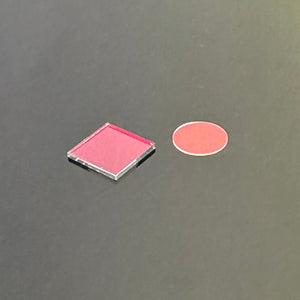
| 2 | CBP850 | 850nm single-bandpass filter | Passes 850nm, blocks visible; 7.0mm circular, 0.3mm thick | 850nm active illumination where a faint LED glow is acceptable and higher sensor QE matters |
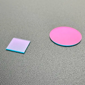
| 3 | CBP940 | 940nm single-bandpass filter | T>90% at 940nm, blocks the visible band | Covert or human-facing 940nm systems where no visible glow is allowed |
| 4 | CLA216-ICR-850BP | Electronic IR-cut / 850nm bandpass switcher | IR-cut and 850nm bandpass in one moving holder, 7.6mm height | Single-camera day/night with full rejection in each mode; pairs with the IR-corrected lens |
| 5 | CDB850 | Dual-bandpass filter (visible + 850nm) | Passes a visible window and an 850nm window in one fixed element | Switcherless day/night on RGBIR sensors at 850nm, no moving parts |
| 6 | CDB941 | Dual-bandpass filter (visible + 940nm) | Passes a visible window and a 940nm window in one fixed element | Switcherless day/night on RGBIR sensors at 940nm, no visible glow |
The ranking follows build order, not price. The IR-corrected lens sits at the top because chromatic focus shift between visible and NIR originates in the glass and cannot be filtered out afterward, while a bandpass center-wavelength mismatch with the illuminator ranks next for costing the most signal of any single choice. Day/night switching hardware ranks last, since most inspection lines run pure NIR and never change modes.
MidOpt (midopt.com) and Edmund Optics both sell established machine vision bandpass and dual-bandpass filter lines, and either is a reasonable source when you need a center wavelength or FWHM outside the Commonlands filter range. For how to match a filter to your illuminator, see bandpass filter center wavelength and FWHM selection, and confirm the lens field of view covers the illuminator beam angle with the field of view calculator before ordering.
CIL122: 12mm M12 IR-Corrected Lens
Day/night and NIR systems on 1/1.7" 8-12MP sensors, all-glass all-metal construction, F/2.4, 43° FoV at 9.2mm sensor diagonal
From $59.00
View CIL122
CBP850: 850nm Bandpass Filter
Single-band bandpass filter for 850nm active NIR illumination, 7.0mm circular / 0.3mm thickness, multiple sizes available
From $9.00
View CBP850
CBP940: 940nm Bandpass Filter
T>90% at 940nm, blocks the visible band for invisible NIR illumination systems
From $9.00
View CBP940
CLA216-ICR-850BP: Electronic Filter Switcher
Electronic day/night switcher: IR-cut filter on one side, 850nm bandpass on the other, 7.6mm height
$12.00
View CLA216NIR system validation checklist
Run this checklist at the real working distance, aperture, and exposure conditions of the deployment. Bench tests at arbitrary conditions routinely fail to predict production performance in NIR systems, because ambient NIR content, filter angle-of-incidence shift, and sensor NIR response all vary between a lab bench and a production line in ways that a quick prototype test will not surface.
- Confirm the IR-cut filter is absent. Remove it physically or verify the camera module was built without one.
- Verify the illumination wavelength. Measure with a spectrometer if the emitter's peak wavelength is not specified on the datasheet.
- Match the bandpass filter to the illumination source. A 20nm mismatch can reduce throughput by 50% or more on a narrow-passband interference filter.
- Capture NIR on and off at the target scene. The on/off contrast ratio on the target feature confirms whether active illumination dominates ambient NIR content.
- Measure signal-to-noise ratio on the real target feature at the operating exposure time and confirm it exceeds the detection algorithm's minimum.
- Check focus stability across wavelengths. If the system also images in visible light, set focus under visible illumination, switch to NIR without adjusting focus, and compare sharpness at the image center and corners on a resolution chart.
- Test with representative target materials, not only calibration targets. NIR reflectance differences from datasheets may not match actual parts or packaging.
- Check behavior at temperature extremes. LED peak wavelength and lens focus can shift with temperature and degrade NIR performance at hot or cold conditions.
- Check illuminator uniformity across the full field of view, not just at the center of the image. NIR illuminators typically fall off toward the edge of their beam angle, and a lens with a wider field of view than the illuminator's effective beam angle will show a dark corner or vignette that has nothing to do with the lens itself. Confirm the illuminator's beam angle equals or exceeds the lens field of view at the intended working distance, and measure signal-to-noise ratio at the corners of the frame, not only at the center, since corner performance is usually the first thing to fail as range increases.
- Re-run validation after any bill-of-materials change. Swapping an LED supplier, a filter vendor, or a sensor revision can shift peak wavelength, quantum efficiency, or filter center wavelength enough to invalidate a prior validation pass, even when every part number on the drawing looks unchanged.
- Document the validated configuration. Record the illumination wavelength, bandpass filter part number, lens model, working distance, aperture, and exposure time. Any change requires re-validation.
よくある質問
What is the difference between 850nm and 940nm in machine vision?
850nm and 940nm are the two standard NIR illumination wavelengths in machine vision. Silicon sensors have higher quantum efficiency at 850nm, so 850nm typically delivers a stronger signal at the sensor for the same illuminator power, but the LEDs emit a faint visible red glow. 940nm produces no perceptible glow under normal operating conditions but needs roughly double the illumination power or exposure time to reach the same signal level, since silicon QE at 940nm is often half or less of its value at 850nm.
What is NIR imaging in machine vision?
NIR imaging uses near-infrared wavelengths, typically 850nm or 940nm, to illuminate and image a scene outside the visible band. A complete NIR system needs a sensor with no IR-cut filter in the optical path, a bandpass filter matched to the illumination wavelength, an NIR light source at that wavelength, and an IR-corrected lens if the system must also produce a sharp visible-light image from the same focus position.
When should engineers use NIR imaging instead of visible light?
Use NIR when visible light does not produce enough contrast on the target feature: printed graphics or barcodes where ink and substrate share similar visible reflectance, specular glare from glossy surfaces, coatings that look uniform under white light but vary in NIR, or environments with unpredictable ambient lighting. NIR is not always better. Validate that the actual materials in the scene produce the expected NIR contrast before committing to the design.
What filters are used for NIR imaging?
Three filter types appear in NIR systems. A single bandpass filter at 850nm or 940nm passes only the illumination wavelength and blocks visible light. A dual-bandpass filter passes both a visible window and a defined NIR window simultaneously in one fixed element, used for switcherless (fixed-filter) day/night imaging on RGBIR sensors. An electronic switcher carries an IR-cut filter and a bandpass filter and moves one into the optical path on command, giving true temporal separation between day and night modes.
Do I need an IR-corrected lens for NIR imaging?
If the system operates only in NIR, focus the lens at the NIR wavelength and correction is not required. If the system must also produce a sharp visible image from the same mechanical focus position, an IR-corrected lens is required. A standard lens has chromatic focus shift between visible and NIR; removing the IR-cut filter does not fix that shift, because it originates in the lens glass, not the filter.
Why does 850nm sometimes show visible glow?
850nm sits close to the edge of human vision, where sensitivity in the deep red falls off steeply but does not fully vanish until roughly 750nm, and the short-wavelength tail of an 850nm LED's broad emission puts a small fraction of its output near that edge. At high drive currents this produces a faint but detectable red glow in dark environments. 940nm sits far enough outside human visual response that it produces no perceptible glow under normal conditions.
How should engineers validate a machine vision NIR setup?
Validate at the actual wavelength, working distance, aperture, and exposure conditions of the deployment. Confirm the IR-cut filter is out of the optical path, verify the bandpass filter center wavelength matches the illumination source, and measure signal-to-noise ratio on the real target feature at operating exposure. If the system also runs in visible light, set focus in visible, switch to NIR without touching focus, and compare sharpness at both wavelengths on a resolution chart before and after the switch.
What is the difference between IR-cut, bandpass, and dual-bandpass filters?
An IR-cut filter blocks wavelengths above roughly 650nm and must be removed for NIR imaging to work at all. A bandpass filter passes only a narrow band centered on the illumination wavelength and rejects everything else, including ambient visible light. A dual-bandpass filter passes both a visible window and a defined NIR window at once in a fixed element, trading full rejection of either band for zero moving parts.
Can NIR imaging reduce glare from printed graphics?
Yes, in many cases. Narrow-band NIR illumination paired with a matching bandpass filter rejects the broadband visible glare that dominates in uncontrolled factory lighting. Dye-based inks used in some printing are transparent to NIR, so printed graphics in dye-based ink can disappear against a reflective substrate under 940nm, which helps when inspecting features under labels but works against you if reading the printed graphic is the goal. Carbon-based ink is the opposite case: it absorbs NIR and stays dark against a reflective substrate, so it keeps its contrast and remains readable.
How do cameras switch between visible and NIR imaging?
Electronic filter switchers use a motor or solenoid to move a filter holder carrying two filters into the optical path. The CLA216-ICR-850BP carries an IR-cut filter and an 850nm bandpass filter in a 7.6mm height package, moved between positions under electronic control. Driven to the IR-cut position, the camera captures visible light only; driven to the bandpass position, it captures 850nm NIR only. A dual-bandpass filter captures both bands at once and cannot separate them temporally. For the switcher to hold focus across both modes, the lens must be IR-corrected.
Is 940nm always the right choice for covert operation?
940nm is generally better for covert operation because the LEDs produce no visible glow, but it is not automatically the right choice. In power-constrained systems (battery-powered embedded cameras, remote installations), the higher illuminator draw at 940nm may be unacceptable. Some engineers use lower drive currents on 850nm LEDs as a partial compromise, which reduces glow without eliminating it. The right answer depends on the system's glow tolerance, power budget, and required detection range, verified against the actual sensor and illuminator, not assumed from a datasheet.
Need help designing an NIR imaging system?
Describe the sensor, working distance, illumination wavelength, and inspection goal. Commonlands engineering can help you choose between 850nm and 940nm, match a bandpass or dual-bandpass filter, and pair it with an IR-corrected M12 lens.