

マシンビジョン向けイメージセンサーの選定:用途に応じた解像度、シャッター方式、およびレンズの組み合わせ
This guide matches resolution, shutter, spectral response, and interface bandwidth to the inspection task, not the megapixel count.

Select an image sensor by working backward from the inspection task. Required feature resolution sets pixel pitch, and motion profile sets shutter type. Illumination strategy sets spectral response, and process speed sets frame rate against interface bandwidth. The lens comes after: it must cover the sensor format and resolve the pixel pitch at the working F-number, or the sensor's resolution is wasted.
How Much Resolution Does the Inspection Task Need?
Resolution requirement comes from the smallest feature you must detect, not an arbitrary megapixel target. A common starting point is 3 to 5 pixels across the feature, though the number you need depends on feature contrast, lens MTF, sensor noise, illumination, and the detection algorithm. A 50µm defect sampled at 3 pixels needs roughly 17µm per pixel in object space, which sets the field of view a given sensor resolution can cover at your working distance.
Work the chain in order. Feature size sets the sampling requirement, and sampling plus field of view sets the pixel count. Pixel count plus format then sets pixel pitch. Jumping to "more megapixels" oversizes the optics, the interface, and the processing budget without improving detection.
A 25MP sensor costs more bandwidth than a 5MP sensor at the same frame rate and bit depth. Extra sampling may improve edge localization, alias control, stabilization, or downsampled output. Measure those benefits against the added cost. Undersizing is the more expensive mistake to discover late: a sensor that cannot resolve the required feature forces a full camera and lens respin.
Calculate required pixel pitch before comparing sensor part numbers. Two sensors with the same megapixel count but different formats have different pixel pitches, and pixel pitch, with the magnification that projects it onto the part and the lens MTF it demands, decides whether the system resolves the feature. Megapixel count alone settles none of that. Commonlands sizes each lens it recommends to the sensor's pixel pitch, not only its format. See spatial resolution in machine vision for the full sampling-to-lens-MTF chain.

Global Shutter vs Rolling Shutter for Machine Vision
Global shutter starts and ends integration for every pixel together, giving all rows one common exposure interval. The capture is not instantaneous, and motion blur still scales with exposure time. Rolling shutter exposes rows sequentially over a readout period lasting microseconds to milliseconds. For a stationary scene, the difference is invisible. For anything that moves relative to the camera (the object, the camera, or both), rolling shutter introduces geometric distortion because the scene changed between when the first row and the last row were sampled.
Strobed illumination needs care on rolling shutter. If the strobe fires while only part of the array is integrating, only those rows record the flash, leaving a bright band. Under strobe-dominated illumination with negligible ambient, the pulse width sets effective exposure and motion blur. Otherwise the programmed exposure accumulates ambient smear too. The exposure setting only has to open a window in which every row integrates at once.
Whether that window exists depends on the sensor timing: an exposure longer than the full readout creates one, and parts with a global reset mode start all rows together instead. Fire the short pulse inside that window to freeze motion.
The tradeoff comes down to motion and the geometric error the task tolerates. Global shutter is the safer default when the camera or object moves during exposure (conveyors, robotics, pick-and-place, strobed illumination, precision measurement): a 200mm/s conveyor moves 0.2mm during a 1ms readout, a real error for a 10µm feature.
Rolling shutter fits when nothing moves during readout (document capture, static label reading, kiosk scanning, cost-sensitive embedded modules). It can still work with motion when readout is short, skew stays inside the task tolerance, or a strobe freezes the scene. Speed, motion direction, triggering, correction, cost, and noise move that line.
| 因子 | グローバルシャッター | ローリングシャッター |
|---|---|---|
| 動きに対する許容度 | No readout skew or wobble. Motion blur still depends on exposure time | 速度および表示時間に応じたスケールのずれと揺れ |
| ストロボ照明 | Compatible with short pulses. Pulse width sets effective exposure when strobe light dominates ambient | Short pulses work only inside a window where all rows integrate together (exposure longer than readout, or a global reset mode, per the sensor timing). Otherwise banding |
| 一般的な費用 | 高くなります。これは、ピクセルごとに1つの蓄積用コンデンサが必要となるため、ダイ面積が増えるからです。 | 特定の解像度およびピクセルピッチでの解像度を低くする |
| 低照度感度 | ピクセルピッチが同じ場合、QEがわずかに低くなることもしばしばある(旧式の設計) | 多くの場合、ピクセルピッチが同じであれば、QEが高く、ノイズが低くなる |
| 一般的なマウントの組み合わせ | Cマウント、大判フォーマット、絞り調整可能 | M12、コンパクトな組み込みモジュール |
| 代表的なセンサー | IMX253、IMX264、IMX568、AR0234 | IMX477、OV5640、IMX415、IMX678 |
Shutter type also correlates with lens mount: global shutter cameras in higher-accuracy industrial systems commonly pair with C-mount lenses, whose adjustable iris ring gives depth-of-field control (practical because illumination is usually programmatically controlled). Rolling shutter sensors dominate compact embedded modules paired with M12 lenses for size and weight. The Commonlands M12 vs C-mount vs CS-mount guide covers the full tradeoff.
Pixel Size vs Lens Resolving Power
Pixel pitch is the center-to-center distance between adjacent pixels. Smaller pixels provide finer sampling, but collect fewer photons per pixel under otherwise equal conditions. The lens needs adequate MTF at the spatial frequencies your task uses. A modest MTF near sensor Nyquist may still be acceptable, and finer sampling can help at lower frequencies. Compare measured task performance rather than matching megapixel labels.
Diffraction caps lens sharpness regardless of lens quality, and it is gradual: contrast falls progressively with spatial frequency, reaching zero only at the optical cutoff, and the falloff grows with F# and wavelength.
Commonlands specifies each lens for a target sensor resolution and pixel pitch. The rating names the sensor class rather than guaranteeing resolved pixels, so confirm the pairing against the lens's measured MTF data at your pixel pitch, working aperture, and field position. The aperture-versus-depth-of-field tradeoff this creates is covered in full in f-number in machine vision.
NIR Sensitivity and Illumination Strategy
Sensor spectral response should follow the illumination strategy, not the other way around. Standard silicon CMOS sensors retain meaningful quantum efficiency into the near-infrared, typically out to 1000–1100nm, but most machine vision cameras ship with an IR-cut filter installed to preserve visible-light color accuracy.
If your system illuminates with 850nm or 940nm LEDs (common for covert lighting, low-visible-light environments, or combined day and night operation), remove the IR-cut filter or specify a NIR-optimized variant. Then confirm the sensor's QE curve at your chosen wavelength rather than assuming uniform NIR sensitivity across parts.
At 850nm, most silicon sensors keep higher QE than at 940nm, at the cost of a faint visible red glow that is sometimes undesirable in public-facing installations. 940nm emitters generally reduce visible red glow compared with 850nm emitters, but visibility depends on their spectrum, intensity, and viewing conditions. Compare the sensor's QE at both wavelengths to estimate the required illumination. Match sensor, filter, and illuminator wavelength as one decision, not three: a NIR-sensitive sensor behind a standard visible bandpass filter gains nothing from the illuminator.
Confirm image circle and lens coating compatibility with your NIR band. See bandpass filter machine vision for lens-side filter selection, and browse the Commonlands filter collection for stocked bandpass and IR-cut options.
Frame Rate vs Interface Bandwidth
The table gives raw line rates. Encoding and protocol overhead reduce usable image-data throughput.
Frame rate is limited by both sensor readout and usable interface bandwidth. For example, 25 million pixels at 8 bits per pixel produce 25MB per frame before transport overhead. A 1Gb/s link has a raw ceiling of 125MB/s, or 5 such frames per second before overhead. Check bit depth, packing, region of interest, lane count, and camera readout limits before committing to a frame rate.
| インターフェース | Raw link rate | ケーブルの長さ | 最適なサイズ |
|---|---|---|---|
| USB3 Vision over a 5Gb/s link | 625 MB/s raw line rate | ~5m | 卓上型および実験室用システム、簡単な統合 |
| GigE Vision over 1Gb Ethernet | 125 MB/s raw line rate | 100m(標準イーサネット) | 解像度やフレームレートが低いシステム、ケーブル長が長い場合、ポートあたりのコストが低い場合 |
| GigE Vision over 10Gb Ethernet | 1.25 GB/s raw line rate | 長距離通信、切り替えコストの増加 | USB 3.0よりも長いケーブル配線が必要な高解像度システム |
| CoaXPress | CXP-12: 12.5 Gbps raw line rate per lane | 複数レーンの構成が利用可能です | Highest resolution and highest frame rate. Requires a specialized frame grabber |
Commonlands engineering can size the lens once the sensor and interface are fixed.
Sensor Format and Lens Coverage
Sensor format is the physical size of the imaging area. The diagonal measurement sets how large a lens image circle you need. If the image circle is smaller than the sensor diagonal, the corners fall outside the rated coverage and receive little to no light, producing vignetting whose severity depends on the lens and how the image circle is defined.
Larger sensor formats capture a wider field of view at a given focal length, or let you use a longer focal length to hold the same field of view with a shallower depth of field. See sensor size and lens compatibility for the format-to-dimension reference and the vignetting math.
| センサーフォーマット | センサーの例 | ピクセルピッチ | 典型的なMP | コモンランズ・レンズ |
|---|---|---|---|---|
| 1/2.8インチ | IMX327 | 2.9µm | 2~5 MP | M12レンズ |
| 1/4インチ | OV5640 | 1.4µm | 5 MP | M12レンズ |
| 1/2.3インチ | IMX477 | 1.55µm | 12 MP | M12レンズ |
| 1/1.2インチ | IMX585 | 2.9µm | 8メガピクセル | Cマウントレンズ |
| 2/3インチ | IMX264 | 3.45µm | 5 MP | Cマウントレンズ |
| 1.1" | IMX253 | 3.45µm | 12 MP | Cマウントレンズ |
| 1/2.6インチ | AR0234 | 3.0µm | 2.3 MP | M12レンズ |
| 1/1.8インチ | IMX547 | 2.74µm | 5 MP | Cマウントレンズ |
| 1.1インチ~1.2インチ | IMX532、GMAX0505 | 2.5~2.74µm | 16~25 MP | Cマウントレンズ |
A lens rated for a 2/3" sensor leaves the corners of a 1.1" sensor well outside its rated image circle, so severe corner shading is the expected outcome at any aperture. The exact falloff depends on the image-circle definition, aperture, and conjugate, so judge it from relative illumination data rather than the format label alone. Stopping down cannot fix a coverage mismatch: the shortfall is geometric, not a depth-of-field effect.
Always match or exceed the sensor format with the lens specification. Oversizing the lens format covers the diagonal, but coverage alone does not qualify the pairing: check CRA against the sensor's microlens and filter stack, MTF and relative illumination at your pixel pitch, mechanical clearance, and the design conjugate, and expect some added cost.
Recommended Lenses by Sensor Format
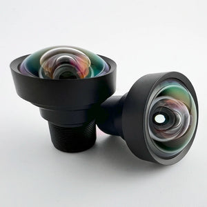
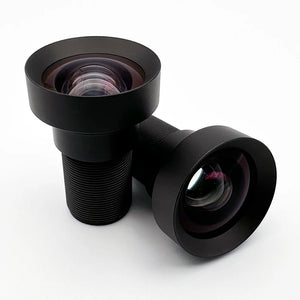
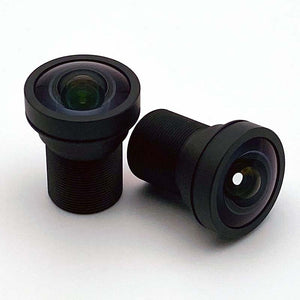
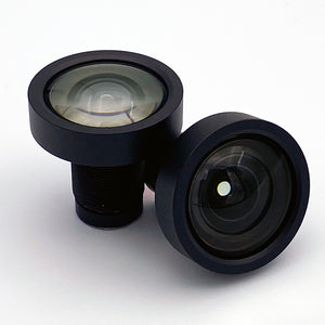
For machine vision sensors up to the 1.1 inch format, Commonlands stocks a matched lens in each band below. Each row lists the stock lens whose rated format and resolution meet or exceed the sensor, taken from the sensor format table above. Coverage comes from each lens's rated image format, not from field-of-view math done on this page.
| センサーフォーマット帯 | おすすめ | マウントとEFL | なぜこれが適しているのか |
|---|---|---|---|
| Embedded (OX08B40, AR0821 class) | CIL059 6mm 低歪み M12 | M12、5.9mm | 9.0mm image circle as designed, 10.4mm maximum, 4–6MP at F/1.7. The fast aperture suits low-light embedded modules. |
| Embedded and sealed, up to 1/2" | CIL034 IP67 3.2mm M12 | M12, 3.2mm | Rated to the 1/2" class (8.0mm reference circle), 5–10MP variants. IP67 sealing is specific to this SKU, not a property of all M12 lenses. |
| 1.1インチ 1200万画素 産業用(IMX253、IMX304) | CIL508 8mm Cマウント | Cマウント、8mm | Rated for 1.1" 12MP at F/2.4 with an adjustable iris. Wider field than the CIL512 at the same working distance. |
| 1.1インチ、1200万画素の産業用カメラ、より長い撮影距離 | CIL512 12mm Cマウント | Cマウント、12mm | CIL508と同じ1.1インチ・12MPの撮影範囲を持ち、作動距離が長いため、より狭い視野を確保できます。 |
| High-resolution sensors with an active diagonal no larger than 17.6mm (for example, IMX541) | CIL542 12mm 25MP Cマウント | Cマウント、12mm | The specified image circle is 17.6mm. GMAX0505 has an 18.10mm diagonal at full 5120 × 5120 readout, so this lens requires a supported crop or separately verified larger coverage. Check measured MTF at the intended aperture and pixel pitch. |
ここで取り上げた1.1~1.2インチフォーマットよりも大きなセンサー(35mmフォーマットのラインスキャンセンサーなど)には、シュナイダーやツァイスなどのメーカーが提供するFマウントまたはM42規格のレンズが必要です。Commonlandsでは、このクラスの製品は取り扱っておりません。
Confirm coverage on your sensor at your working distance with the field of view calculator, and check the sensor diagonal against each lens image circle before you commit.

Technical references
- Optikos, How to Measure MTF and Other Properties of Lenses
- ams OSRAM, High-power Emitters for Illumination
よくある質問
マシンビジョンに適したイメージセンサーはどのように選べばよいでしょうか?
データシートではなく、まず検査タスクから検討を始めましょう。解像しなければならない最小の細部、露光中に被写体やカメラが動くかどうか、照明帯域(可視光または近赤外線)、そしてプロセスに必要なフレームレートを明確にします。これら4つの要件を明確にすることで、メガピクセル数だけを比較する前に、候補となるセンサーのリストを絞り込むことができます。
グローバルシャッターとローリングシャッターの違いは何ですか?
Global shutter gives every pixel one common integration interval: all rows start and stop exposing together, though the capture still has finite duration, so motion blur depends on exposure time. Rolling shutter exposes rows sequentially over a readout period lasting microseconds to milliseconds. For a static scene the difference is invisible. For anything moving relative to the camera, rolling shutter introduces skew, wobble, or flash banding.
マシンビジョンには、どの程度のピクセルピッチが必要ですか?
A common starting point is 3 to 5 pixels across your smallest feature, adjusted for contrast, lens MTF, sensor noise, and your detection algorithm. From there, work backward through your magnification to the required pixel pitch at the sensor. Solve aperture and pixel pitch together, not independently.
私の用途には、NIR感応型センサーが必要でしょうか?
Choose a NIR-sensitive sensor and remove or bypass the IR-cut filter when your illumination uses 850nm or 940nm LEDs, common for low-visible-light environments or combined day and night operation. Confirm the sensor's QE curve at your wavelength rather than assuming uniform NIR sensitivity.
Commonlandsのレンズを自分のセンサーに合わせるにはどうすればよいですか?
Identify your sensor format and pixel pitch, then choose a Commonlands lens rated for that format or larger.
Use the Commonlands field of view calculator to confirm coverage at your working distance, and the depth of field calculator to check depth of field at your aperture. Contact Commonlands engineering if you are still unsure.
お使いのセンサーに合うレンズ選びでお困りですか?
Commonlands Engineeringでは、お客様がハードウェアを決定する前に、センサーフォーマット、ピクセルピッチ、シャッターの種類、作動距離に合わせて最適なレンズをご提案いたします。