

Lens Chief Ray Angle (CRA) and CRA Mismatch: How to Match a Lens to Your Image Sensor
A lens can cover the sensor format, thread on cleanly, and meet its MTF spec, yet still ship magenta corners. Chief ray angle is the compatibility check most spec reviews skip.

Chief ray angle (CRA) is the angle between the optical axis and the chief ray (the ray from an off-axis scene point through the center of the aperture stop), measured at the image plane. CRA mismatch is when the lens's ray angles deviate from the incidence angles the sensor's microlens array was built to accept, producing corner color shading, crosstalk, and illumination falloff.
Commonlands shortlists by matching lens edge CRA to the sensor's design CRA within roughly ±3°. That is a screening filter, not an acceptance limit: the real tolerance depends on the full ray cone at each field point, and flat-field plus corner MTF measurements settle it.
What is the chief ray angle (CRA) of a lens?
Chief ray angle (CRA) is the angle between the chief ray (the ray from an off-axis object point that passes through the center of the aperture stop) and the optical axis at the image plane. CRA often increases toward the edge, but its field dependence can be nonlinear or non-monotonic. Request the full CRA-versus-image-height curve rather than assuming the maximum occurs at the edge.
The datasheet CRA curve plots that angle against image height, and to first order the exit pupil position sets it:
Exit pupil distance is the design lever, and vendors often quote it even when the full CRA curve is not. Sit it far from the image plane and chief rays stay nearly perpendicular (approaching image-space telecentricity), but the lens needs larger rear-group apertures and a longer body. Compact modules push it close to the sensor to cut z-height, and edge CRA climbs to 25–35° in mobile-heritage designs.
CRA is a separate axis of compatibility from focal length and coverage. The Commonlands field of view calculator and EFL calculator settle the geometry. CRA decides whether that light reaches the pixels efficiently.

What is CRA mismatch between a lens and a sensor?
CRA mismatch is the difference between the lens's chief ray angle and the incidence angle the sensor's microlenses were designed to accept at the same image height. Each pixel sits under a microlens. Sensor designers shift those microlenses laterally toward the optical axis so that oblique light still lands on the photodiode.
A 0° CRA sensor has microlenses centered over each photodiode and expects near-perpendicular light. A 28° CRA sensor offsets its microlenses progressively toward the array center, tuned for a lens that tilts edge bundles steeply. Datasheets publish this acceptance curve against image height, sometimes linear and sometimes shaped for one lens family.

CRA mismatch is a design incompatibility, not an assembly defect. Sensor tilt, decenter, and defocus are mechanical errors with their own diagnostics, covered in the Commonlands sensor alignment guide. They interact: tilt makes the mismatch asymmetric, so one corner runs at a larger effective angle than its opposite.
How does CRA mismatch cause color shading and vignetting?
CRA mismatch reduces light capture, drives optical crosstalk between neighboring pixels, and produces radial color shading (often a magenta or green corner tint) plus illumination falloff beyond the lens's own relative illumination roll-off. Because the loss differs per color channel on Bayer sensors, luma-only flat-field correction lifts brightness but leaves a chroma error.
The color shading is a Bayer effect. An oblique ray that enters through a green filter can land partly on the neighboring red or blue photodiode. Each channel also has a slightly different acceptance geometry through the cover glass stack, so the crosstalk is asymmetric across channels.
That is why RGB sensors show CRA mismatch first. A monochrome pixel has no color filter array to unbalance, so the error costs signal and contrast without a color signature. It still loses that light: microlens, metal, and window losses plus reflection and crosstalk all rise with angle. Monochrome buys headroom, not immunity. Push an RGB part past its limit and the tint deepens while the image signal processor's (ISP's) corner gain amplifies noise.

Even a matched pairing loses corner illumination to the lens's own relative illumination roll-off. Cosine-fourth models that roll-off only to first order under rectilinear projection. It is not a law. The MTF curve guide covers separating CRA shading from ordinary aberration falloff. Pupil aberration, projection, telecentricity, vignetting, distortion, and the sensor's angular response push measured curves above or below it.
Mismatch then adds channel-dependent loss on top, which is why mismatched corners look both dark and tinted. Baseline falloff and image circle margin are covered in the relative illumination guide.
Why do image sensors ship in multiple microlens CRA variants?
Sensor manufacturers sell the same silicon with different microlens shift profiles, called CRA variants, under different ordering codes. The variant, not just the sensor model, decides which lenses pair cleanly.
The driver is packaging: thin modules force the exit pupil close to the sensor, while industrial cameras have room for near-perpendicular chief rays.
| Application class | Typical design CRA | CRA profile | なぜ |
|---|---|---|---|
| Mobile and consumer | 25–35° at image edge | Non-linear, tuned to a lens family | Enables thin modules under 10mm z-height |
| Industrial and machine vision | 0–15° at image edge | Linear | Matches conventional glass optics with distant exit pupils |
Put the microlens variant on the purchase order: two reels of the same sensor model with different CRA variants behave like different parts on the line. If the sensor choice is still open, compare each variant's angular response with the candidate lens. A low nominal CRA does not by itself mean greater mismatch tolerance. The Commonlands sensor reference pages list format dimensions and pixel specifications for common parts.
What CRA tolerance should you target?
There is no universal CRA tolerance. What a pairing accepts depends on the full ray cone at each field point (hence on f-number), the wavelength band, the pixel stack and cover glass, the field height in question, and how much shading and corner MTF loss the application allows. A nominal CRA value does not specify angular acceptance. Use the checks below to establish whether the pairing meets the application's limits.
| Check | Data needed | Acceptance measure |
|---|---|---|
| Field dependence | Lens CRA curve and sensor angular response at matching image heights | Corner and center signal within the system limits |
| Ray cone | Working f-number and pupil behavior | Acceptable response over the full incident cone |
| Spectrum and color | Response in each operating wavelength band | Color shading and MTF within the task limits |
A monochrome sensor has no color filter array to unbalance, but its angular response still needs testing: oblique light is still clipped by the microlens, passivation, metal layers, and the window stack, and crosstalk still costs corner MTF. Only the color signature disappears.
NIR needs extra care, because microlens angular response is wavelength dependent, so a pairing that passes in visible light can shade differently at 850nm. The Commonlands NIR imaging guide covers band-specific validation.
CRAの不一致はソフトウェアで修正できますか?
Only partially. A shading calibration works in fixed lighting, but it encodes the spectrum of the light source it was built under. Change the illuminant (daylight to LED) and the per-channel corner loss changes shape, because the crosstalk is wavelength dependent, so the cast returns in a different color. Software also cannot recover lost signal: corner gain raises noise, and edge contrast that was never captured is gone.
The practical hierarchy Commonlands recommends: fix the mismatch optically with a compatible lens or the right sensor CRA variant, then let the ISP clean up the small residue. A small residual is a routine calibration task. A gross mismatch is a science project that may still miss quality targets in some lighting.
How do you test for CRA mismatch in the lab?
Test with flat-field captures and corner MTF, not datasheet values alone. Photograph a uniform white target under representative lighting, map center-to-corner brightness per color channel, then run slanted-edge SFR following the ISO 12233 procedure at the corners.
Corner falloff and soft corners alone do not diagnose CRA. Aberrations, optical and mechanical vignetting, sensor tilt, a nonuniform target or illuminant, the filter stack, and ISP shading correction all produce the same picture. The CRA signature is per-channel and radial, so compare channels, change illuminant spectrum, and keep a reference lens on the same rig before blaming the microlens match.
- Define constraints first. Sensor model and exact CRA variant, pixel size, datasheet CRA curve, cover glass stack, wavelength band, target F#, and the ISP correction overhead you can accept.
- Build a lens shortlist. Screen for image circle coverage and focal length, then filter for CRA compatibility against the sensor curve. Choose the low-CRA control from a measured or ray-traced CRA-vs-image-height curve. Without one, measure before trusting any candidate as a control. Neither field of view nor focal length predicts image-side CRA on its own.
- Capture flat fields. Uniform white target at two or more exposure settings per candidate. Compute per-channel imbalance at 80% of image radius as the primary CRA indicator.
- Run corner MTF. Slanted-edge target at the corner under production-like focus, temperature, and illumination. CRA crosstalk shows up as contrast loss near Nyquist (0.5 cycles per pixel).
- Decide go/no-go. Accept the candidate needing the least correction, then, after shading correction, reject any whose corner SNR at your darkest specified illuminance or whose corner MTF at your target frequency falls below spec.
Normalize what you can: same working distance, same image height for every measurement, same illuminant and exposure. Most M12 lenses have a fixed aperture, so candidates will not share an f-number. Record each lens's working f-number and treat the comparison as confounded by cone angle and intrinsic aberration until you can equalize them. The depth of field calculator helps pick a working distance that keeps every candidate in usable focus.
For measured MTF evidence on a calibrated bench, the Commonlands Trioptics HR2 MTF testing service ($199) compares candidates before a design commitment.
How do you match M12 lenses to Sony IMX sensors?
Confirm the active-area diagonal, pull the CRA curve for the exact IMX variant from the datasheet, shortlist 2–3 M12 lenses that cover the format, and benchmark flat fields and corner MTF on one rig. Lock the design on the lens that needs the smallest correction gain map.
Sony IMX sensors dominate compact embedded vision, and many M12 lenses target IMX-class formats. That does not mean any M12 lens pairs cleanly with any IMX part: acceptance CRA varies across the family and across microlens variants.
Confirm the diagonal from the datasheet active-area dimensions, not the nominal format name. The CMOS sensor size guide explains the naming gap. Then check whether the datasheet gives a full-field acceptance curve or only a recommended maximum edge CRA, and use the full curve when you have it.
Draw candidates from the M12 lens collection. For inspection work on 1/2" and smaller formats, the Commonlands 6mm rectilinear M12 lens (CIL062) is a predictable-edge option at −2% rectilinear distortion, referenced to its 8.8mm circle. As a separate hypothetical example, 2% distortion at 4mm image height corresponds to an 80µm displacement. Do not transfer a distortion value specified at an 8.8mm circle to that smaller field without the measured curve.
For mixed visible and NIR illumination in robotics and outdoor systems, the Commonlands CIL239 fisheye shifts focus by less than 8 microns from 550nm to 850nm. Whether that counts as holding focus is a system question: on a fast lens with small pixels, 8 microns can span several depths of focus, so check it against measured through-focus MTF at your working f-number.
Image-side CRA follows the exit pupil position and the prescription, so read the measured or ray-traced CRA-versus-image-height curve rather than inferring it from EFL or field of view.
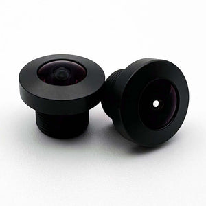
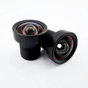
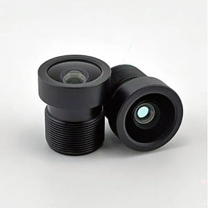
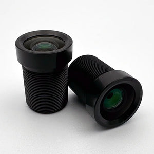
Lenses and testing services for CRA-sensitive designs

よくある質問
Commonlands matches lens CRA to sensor microlens designs when recommending lenses.
What is the chief ray angle in a camera lens?
Chief ray angle is the angle between the optical axis and the chief ray (the ray from an off-axis scene point that passes through the center of the aperture stop), measured at the image plane. It increases with image height, so lens datasheets usually quote the maximum value at the edge of the image circle.
What causes CRA mismatch between a lens and a sensor?
CRA mismatch occurs when the lens's chief ray angle at a given image height differs from the incidence angle the sensor's shifted microlenses were designed to accept there. Common causes include pairing a mobile-heritage high-CRA sensor variant with an industrial low-CRA lens, cover glass stack differences, and tight z-height packaging constraints.
Why are RGB sensors more sensitive to CRA mismatch than monochrome sensors?
The Bayer color filter array converts angular error into per-channel imbalance, which shows up as visible color shading. A monochrome part has no color channels to unbalance, so it leaves more headroom. It does not collect every photon: microlens, passivation, metal, and window losses plus reflection and crosstalk still grow with angle, so signal and corner sharpness fall off there too.
What CRA tolerance should I target for machine vision cameras?
There is no universal number. Commonlands screens candidates by matching lens edge CRA to the sensor's design CRA within about ±3°, which is a shortlisting filter, not an acceptance limit. What a pairing tolerates depends on the full ray cone at each field point, so on f-number, plus wavelength, pixel stack, cover glass, and the shading and corner MTF loss you accept. Settle it with flat-field and corner MTF tests.
How do I match M12 lenses to Sony IMX sensors?
Confirm the active-area diagonal, pull the CRA curve for your exact IMX variant from the datasheet, shortlist 2–3 M12 lenses with sufficient image circle, then benchmark RGB flat fields and corner MTF on the same rig. Choose the lens that meets image quality targets with the smallest ISP correction map.
Get a CRA-matched lens recommendation
Send your sensor part number (including the CRA variant suffix) plus working distance and target field of view, and our San Diego engineering team will shortlist compatible lenses. Commonlands is ISO 9001:2015 certified, and orders placed before 12 PM PST ship the same day.